1. About this guide and your exact revision
Your Manufacturing Pack turns one saved Cabinet Designer revision into a practical set of workshop information. This complete guide follows the document in page order, explains what each section contains, what to check and how to use it, and points out common mistakes before they reach the workshop.
A pack belongs to one exact, immutable saved revision. Its dimensions, materials, construction options, quantities, edges and connection positions come from that revision. If you make a manufacturing-affecting change, save the new revision and generate a new pack; never mix pages from two revisions.
An unchanged revision that is already entitled can be viewed or downloaded again without using another Design Credit.
- What this section is
- The identity and scope rule for the complete document.
- What to check
- The cabinet reference, revision, overall size, materials and chosen construction match the cabinet you intend to make.
- How to use it
- Keep the complete pack together and mark the same revision reference on workshop notes.
- Common mistake
- Reusing an older cut list or panel page after changing the design.
2. Before You Manufacture
Do this check before cutting, drilling or ordering final hardware. Stop if any value looks wrong, is unclear or does not match the saved cabinet.
- Check the overall width, height and depth against the intended installation space.
- Check every component size and quantity against the cabinet you expect.
- Check each material and actual sheet thickness.
- Check selected edge treatment and every treated physical edge.
- Check fixing positions, datums, face orientation and part codes.
- Confirm tool, jig, cutter and hardware setup against the current manufacturer's instructions and test on spare material.
- Do not manufacture if anything looks wrong or unclear; report the issue first.
3. Cover, project summary and finished 3D view
The cover identifies the Cabinet Designer, pack type, saved revision and generation state. It combines the finished 3D cabinet view with a summary of the overall dimensions, construction, material groups, fronts, shelves, plinth, connection method and edge-treatment state that apply to this revision.
- What this page is
- Your first whole-cabinet visual and revision check.
- What to check
- The cabinet type, overall dimensions, front arrangement, shelves, back/top/plinth choices and material/thickness groups.
- How to use it
- Compare it with the saved Designer preview and intended finished cabinet before reading part-level information.
- Common mistake
- Treating the 3D picture as a dimensioned drawing. Use the cut list and panel pages for measurements.
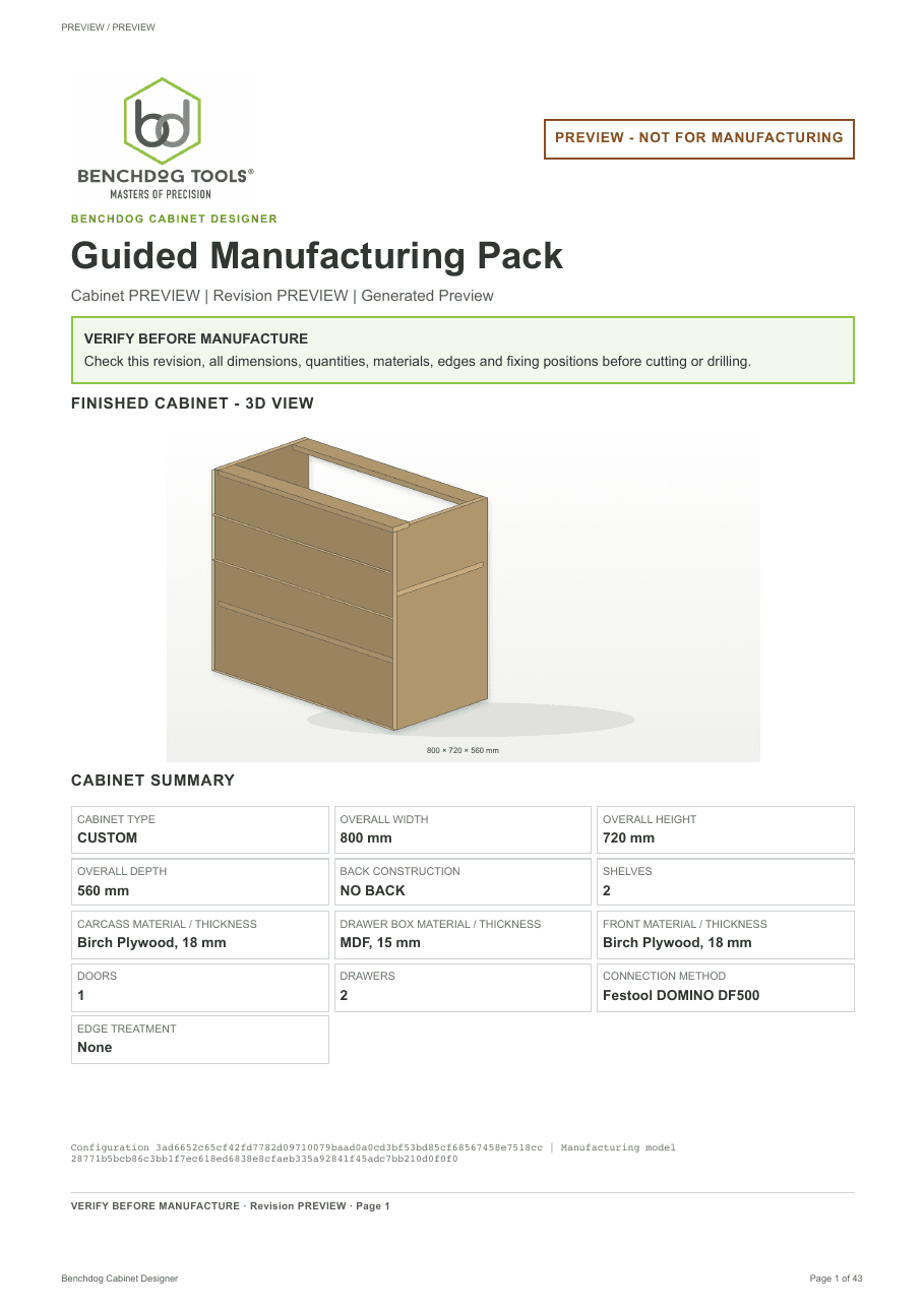
Current pack cover and finished cabinet check.
- Pack and revision identity
- Finished cabinet view
- Cabinet summary
4. Exploded view and part codes
The exploded view separates the cabinet components so you can see how carcass parts, shelves, rails, fronts, drawer parts, backs and plinth parts relate. Leader lines name parts with the same codes used everywhere else in the pack.
Part codes are reference labels. For example, CAB-LS is the left side, CAB-RS is the right side, CAB-BTM is the bottom, CAB-SH-001 is a shelf and a drawer-side code identifies both the drawer number and the side. Follow the same code from the exploded view to the cut list, component overview and individual drawing.
- What this page is
- An assembly relationship and part-identification view.
- What to check
- Every expected component appears and its code can be traced to the cut list and drawing.
- How to use it
- Label cut components with their part code as soon as they are made, then use this view during dry fit.
- Common mistake
- Using apparent spacing in the exploded picture as an assembly dimension. Separation is visual only.
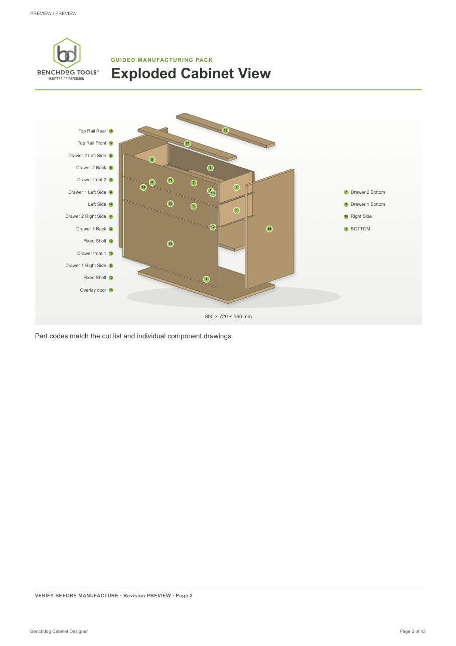
The exploded view is an assembly reference, not a cutting drawing.
- Separated cabinet components
- Part-code labels
- Matching leader lines
5. Panel cut list
The cut list is the workshop index for all manufactured parts. Read a row from left to right and keep the code with the material from marking out through assembly.
Length and Width follow the orientation stated by the pack rather than simply meaning the longest and shortest edges. Grain direction is not assumed: only treat grain as controlled where the current drawing or material information explicitly shows it.
- Code
- The stable part code that links the row to the overview, drawing and assembly steps.
- Part Name
- The plain-language role, such as Left Side, Door or Drawer 1 bottom.
- Qty
- How many manufacturing-equivalent copies are required. MAKE X OF THIS PART means make the shown part X times.
- Length and Width
- The rectangular cut size in the orientation used by the pack. Read both values; do not assume the larger value is always the same workshop direction.
- Thickness
- The required stock thickness for that component group.
- Material
- The selected carcass, back, drawer-box or front material assigned to that part.
- Edge Treatment
- Selected treatment for the part, or None when no treatment is required.
- Common mistake
- Making one part because there is one drawing while missing a quantity greater than one.
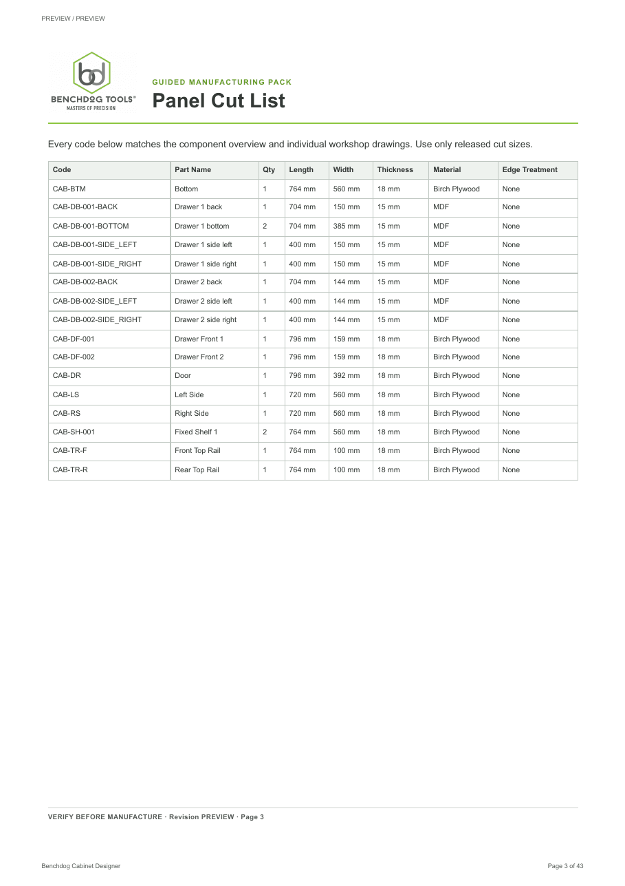
Read every row across before marking or cutting stock.
- Part code and name
- Quantity
- Length, width and thickness
- Material and edge treatment
6. Component overview — flat part reference
This proportional flat reference groups the current parts by role and shows their code, name and overall size. It helps you account for the component set and recognise similar-looking parts.
- What this page is
- A compact visual index of the manufactured component set.
- What to check
- Part groups, codes and overall proportions agree with the cut list.
- How to use it
- Use it when sorting and labelling parts before drilling or assembly.
- Important
- It is NOT a sheet nesting layout, cutting plan or proof that the displayed gaps are waste allowances.
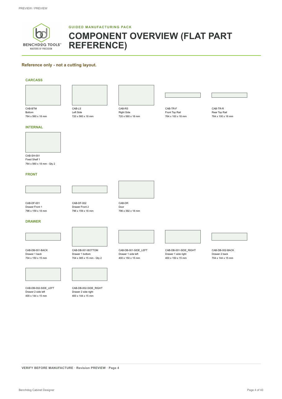
Reference only: this page is not a sheet nesting or cutting layout.
- Not a cutting layout warning
- Role groups
- Part code, size and proportion
7. Connection overview and fixing centres
The connection overview shows the selected connection method, its joint application, the two participating parts, fixing centres from the stated joint datum, connector quantity and layout source. The same exact centres are repeated on the applicable panel drawings.
A connection centre is a marked location for the selected joint. A list such as 37 mm, 199 mm, 361 mm and 523 mm means that every centre is measured from the named datum/reference edge. Those numbers locate the joints; they do not specify cutter depth or tool setup.
- What this page is
- A cabinet-wide index of deterministic connection positions.
- What to check
- The selected method, participating parts, quantity, centre list and stated datum direction for each joint.
- How to use it
- Confirm the joint plan here, then mark or machine each part from its individual drawing and labelled datum.
- Common mistake
- Measuring centres from the opposite edge or treating centre positions as tool depth, diameter or jig settings.
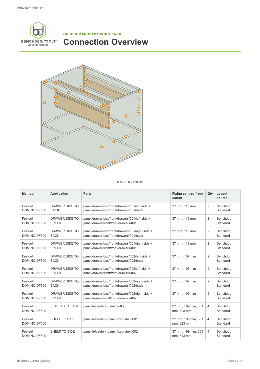
The overview links each selected method to parts, centres, quantity and layout source.
- Connection markers
- Fixing centres from datum
- Method and participating parts
8. What You Need and the material check
This page groups stock by material and thickness, states how many parts are ready in each group, lists neutral customer-selected hardware responsibilities and records relevant supplies, connectors and safety items.
Check the material itself before making several parts. A board sold as nominal 18 mm may vary slightly, so confirm the actual stock and make sure the intended tools and hardware suit it.
- What this page is
- A workshop preparation and stock-group check, not a live price or availability list.
- What to check
- Actual stock matches every material/thickness group and suitable hinges, runners, fixings, consumables and safety equipment are available.
- How to use it
- Separate sheet stock by material and thickness before transferring cut-list rows to it.
- Common mistake
- Using carcass stock for the back, fronts or drawer box when the revision assigns a different material or thickness.
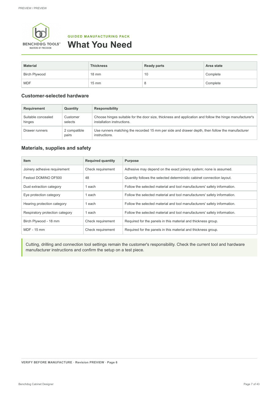
Use this page as a stock and responsibility check before starting work.
- Material and thickness groups
- Customer-selected hardware
- Supplies and safety items
9. Edge-treatment schedule
The edge schedule lists only treatments selected in the saved design. Where treatment exists it identifies the part, physical edge, treatment, nominal thickness and finished edge length. None means no edge treatment is required for that cabinet or part.
In V1, panel cut dimensions are not automatically reduced by the edge-band thickness. Use the calculated cut and finished sizes shown in the pack and do not invent a compensation allowance.
- What this page is
- The authoritative schedule of selected treated edges.
- What to check
- Part code, physical edge, band/treatment, thickness and required length.
- How to use it
- Mark treated edges after cutting and before applying the selected process; keep front/rear/left/right orientation visible.
- Common mistake
- Adding treatment to an exposed edge that the customer did not select, or treating None as a pending process.
The schedule records selected treatment only; None means no edge treatment is required.
- Edge schedule heading
- Recorded edge-banding state
- Plain-language result
10. Individual panel drawings, dimensions and datum
This is the largest section of most packs. Every unique manufacturing part receives a dimensioned page; truly identical manufacturing parts may be grouped and show the required quantity prominently.
Finished Size states the required component size for this revision. Dimension lines show overall length and width, while the side elevation shows thickness. Datum A is the highlighted intersection of labelled reference edges. Face A/Face B and front/rear/top/bottom/left/right labels prevent mirrored or reversed marking.
The arrows and extension lines define the two points between which each dimension applies. A fixing-position dimension starts at the stated datum rather than at the nearest-looking edge. The workshop checklist can be used to confirm the part code, cut size, face/datum marking, connection centres, dry fit and completed quantity.
One drawing is grouped only when every manufacturing fact is identical. A change to size, material, edge treatment, groove/rebate or connection position creates a separate manufacturing drawing.
- What this page is
- The working drawing for one unique manufacturing part.
- What to check
- Code, name, quantity, material, thickness, finished/cut size, status, orientation, datum, edge treatment and every applicable fixing centre.
- How to use it
- Cut to the released size, label the part and Face A, mark Datum A, keep the stated orientation, then transfer positions from the labelled datum.
- Common mistake
- Rotating or flipping the part after marking without moving the datum reference with it.
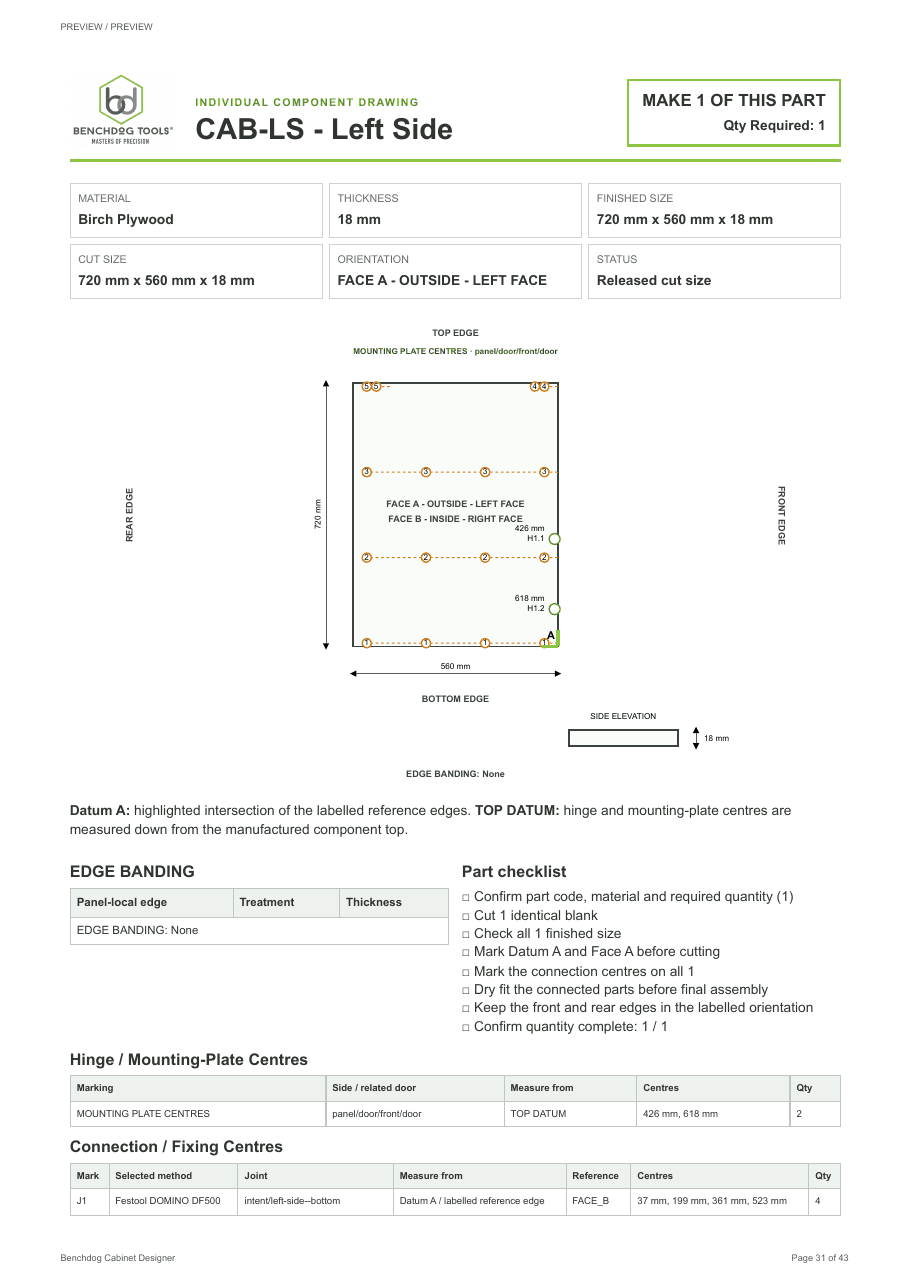
A typical individual panel drawing. Always read the facts and datum before using the marks.
- Part code, quantity and finished size
- Datum A and labelled orientation
- Overall dimensions
- Connection and fixing-centre table
11. Door drawings and generic hinge centres
Door pages record the final door code, quantity, material, thickness, finished size, visible/inside face and edge orientation. Where the current revision supplies generic concealed-hinge centre guidance, the door and matching cabinet-side mounting-plate centre heights must align physically.
The pack does not choose a hinge or supply manufacturer-specific cup setback, boring depth, plate-hole pattern or screw specification. Check those details against the actual hinge and jig instructions.
- What to check
- Door quantity, finished width/height, hinge side, visible face, edge schedule and matching centre heights.
- How to use it
- Make the final rectangular front first, then use the centre guidance with the selected hinge manufacturer's fitting method.
- Common mistake
- Treating a generic centre mark as a complete concealed-hinge boring pattern.
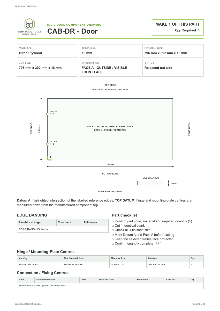
Door drawings use the same part-code, face, edge and datum language as carcass panels.
- Door identity and quantity
- Visible and inside face orientation
- Finished door dimensions
12. Drawer parts, fronts, bottoms and runner clearance
Drawer pages keep each drawer ordinal together: decorative front, left side, right side, back, optional structural box front and bottom. A three-sided box uses the applied decorative front to close the box; a four-sided box has its own structural front behind the decorative front.
Drawer-box width is based on the actual opening less the saved left and right runner clearances. Bottom construction, material, thickness, inset, groove or rebate intent follow the selected revision and may change bottom size and the surrounding parts.
In simple terms: opening width minus left clearance minus right clearance equals drawer-box width. No branded runner is required, but the saved clearances must match the instructions for the runner you actually fit.
- What to check
- Drawer number, box type, part set, box material/thickness, front material/thickness, runner clearance, depth and bottom construction.
- How to use it
- Keep all parts with the matching drawer number and dry assemble the complete box before fitting the decorative front or runners.
- Common mistake
- Mixing parts from two drawers, forgetting the structural front on a four-sided box, or substituting runner clearance after the parts are cut.
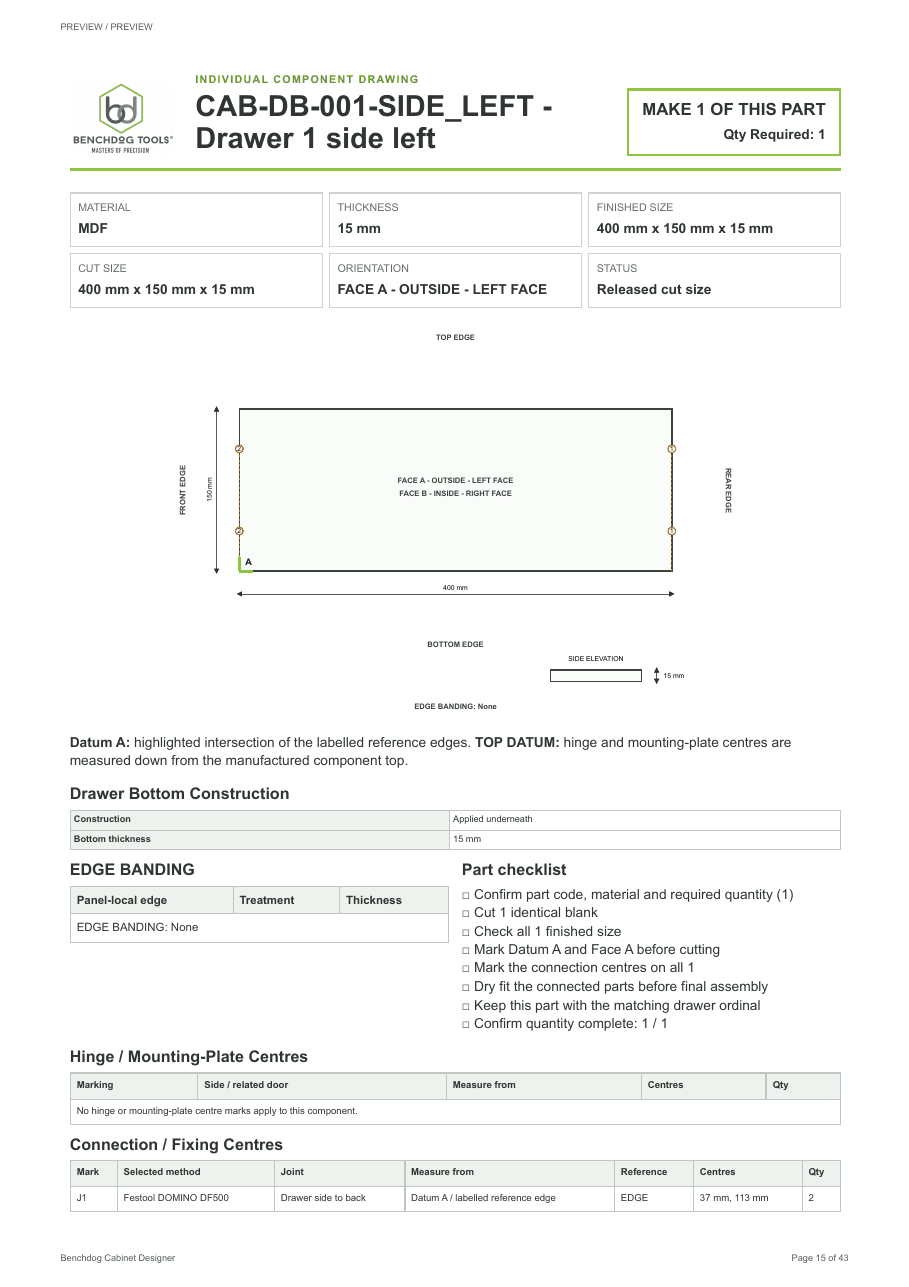
Keep every drawer part with its matching drawer ordinal.
- Drawer and component identity
- Finished size and material
- Front and rear orientation
13. Drawer-bottom drawing
The bottom has its own manufacturing page because material, thickness, size and construction can differ from the drawer sides. The page records the final bottom configuration for the exact revision, including machining intent where the selected construction requires it.
Current construction choices are Applied Underneath, Flush Fitted, Recessed in Grooves and Rebated Edges in Grooves. Depending on the choice, the drawing can include an inset, groove, rebate, clearance or a changed bottom size. Use only the details shown for the selected revision.
- What to check
- Drawer number, bottom material, thickness, finished size, front/rear orientation and any groove, rebate or inset detail shown.
- How to use it
- Keep the bottom with its matching drawer and test the construction fit on spare material before committing all box parts.
- Common mistake
- Assuming every drawer bottom is applied underneath or the same thickness as the sides.
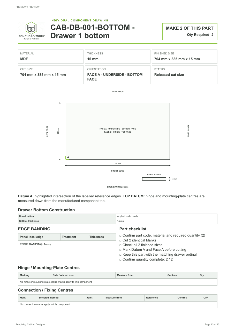
The drawer-bottom page records the actual bottom configuration selected for that revision.
- Drawer-bottom identity
- Bottom material, thickness and size
- Front datum and orientation
14. Shelves, back, plinth, top and support rails
These parts use the same drawing rules as carcass panels. Shelf depth is measured from the usable rear datum and extends forwards. A recessed or rebated back and any service void affect that usable rear position. Plinth setback is measured rearwards from the cabinet front datum to the front face of the front plinth. A full top or the selected support rails appear as their own canonical parts.
- Shelves
- Check width, selected depth, rear alignment, fixed/adjustable intent and selected treated edges.
- Back
- Check applied, recessed/rebated or no-back construction, material, thickness and service-void relationship.
- Plinth
- Check height, setback, component size and that the 3D/cut-list/drawing identities agree.
- Top / rails
- Check whether the cabinet uses a full top, two support rails or no top, plus the saved rail width and span. The current default for two support rails is 100 mm; a customer-saved override replaces that default.
- Common mistake
- Measuring a shallow shelf from the cabinet front instead of aligning it to the usable rear datum.
15. Assembly, workshop workflow, limits and help
The Assembly Overview gives a practical order, the part codes used at each step and orientation notes. Final Checks repeats the essential verification points and identifies any genuine unresolved item for the revision.
- Experienced-user shortcut
- Jump to Cut List → Individual Panel Drawings → Connection Overview → Edge Schedule, but still confirm the cover revision and Final Checks.
- What the pack does not tell you
- It does not verify the installation site, actual stock thickness, machine condition, tool safety, hardware suitability, manufacturer-specific boring/setup or legal/building requirements.
- FAQ — Can I reuse it after an edit?
- No. Generate a pack for the new manufacturing revision. Re-downloads of the unchanged entitled revision use no further credit.
- FAQ — Is the component overview a nesting plan?
- No. It is a proportional part reference only.
- FAQ — Why does one drawing show Qty 3?
- It represents three genuinely identical physical parts. Make three copies and keep the same code and orientation with each one.
- FAQ — Why are hinge holes not fully dimensioned?
- The pack provides generic hinge and matching mounting-plate centres where applicable. Cup setback, boring depth, plate pattern and other hardware settings come from your chosen hinge manufacturer.
- FAQ — Why is edge banding shown separately?
- The schedule gives one cabinet-wide checklist, while each panel drawing confirms the selected treatment on that exact physical edge.
- FAQ — Can I use a different tool, hinge or runner?
- Yes, if it suits the design, material and application. Keep the Designer's positions and dimensions, then follow the selected product manufacturer's setup and safety instructions.
- FAQ — Why is the pack tied to a revision?
- Changing a manufacturing input can alter sizes, quantities or marks. The immutable revision keeps every page traceable to one exact design.
- FAQ — What if a value looks wrong?
- If dimensions appear inconsistent, do not choose one or average them. Stop, record the revision and affected page/part code, then report the issue.
- 1. Confirm the revisionMatch the cover to the saved cabinet and intended site dimensions.
- 2. Prepare stockSeparate and verify each material/thickness group from What You Need.
- 3. Mark the cut listWork row by row, including quantity and edge-treatment status.
- 4. Label every partKeep the part code, Face A and Datum A with each component.
- 5. Apply the edge scheduleTreat only selected physical edges and keep orientation clear.
- 6. Transfer connection positionsUse the individual drawing and measure from its labelled datum.
- 7. Prepare fronts and drawersKeep drawer ordinals together and verify hinge/runner manufacturer setup separately.
- 8. Dry fitFollow the assembly order and confirm orientation, alignment and squareness.
- 9. Recheck before fasteningCompare the dry assembly with the cover and exploded view.
- 10. Keep the packRetain the complete revision-specific document with the finished job.
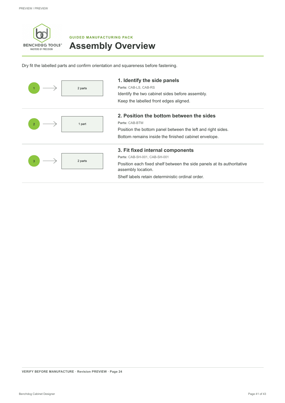
Use the assembly overview after identifying and dry-fitting all labelled parts.
- Assembly step number
- Parts used in this step
- Relationship and orientation notes